Friday, May 31, 2013

Week 9 Update

We have completed both models of the gliders and have begun testing. Here are the images of the gliders thus far:


Figure 1: Control Glider & Modified Glider (left to right)
We have also completed an updated version of the AutoCAD drawings of the aircraft.

Figure 2: AutoCAD Plans of Gliders
Having finished the bulk of the project, we are now conducting testing and will post our conclusions soon.

Friday, May 24, 2013

Week 8 Update

We have finished a flying physical model for the control. Pictures will be added shortly.

It was noted that the aircraft created too much lift without external weights added to the nose-portion of the model. Testing was held off due to windy conditions and the fact that the Armory was closed. As we get closer to finishing all models, testing will begin, allowing for data collection.

The models were extended to be 24" instead of the 14.4" as seen below. The CAD plans will be updated and posted shortly. Working with the foam continues to be a complicated task, but there has been progress in creating all models needed.

Saturday, May 18, 2013

Week 7 Update


Physical Work:

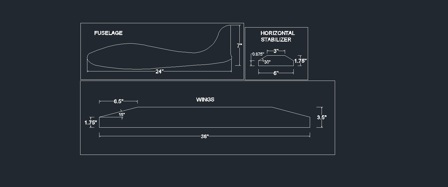
The group has begun working on the final models of the gliders—specifically the control (models & modifications can be seen below in Figure 2). The specifications for each model are still to be entirely determined, but the preliminary design can be seen in CAD form in Figure 1.

Figure 1: AutoCAD Drawing of Aircraft Design

Figure 2: Statistical Analysis of Aircraft Tests


Statistical Analytical Table (See Figure 2):

            The table seen in Figure 1 (not labeled as a table, as this is simply a picture) outlines the criteria that we will be working with throughout the flight tests as well as the individual modifications. There will be four modifications:
·         Flaps and Ailerons
·         Horizontal Stabilizer Shape & Size
·         Weight Added and Distribution to Model
·         Wing Design
These modifications will be tested against four criteria:
·         Flight Time (in seconds)
·         Distance Traveled (in feet)
·         Deviation from Start Point (in degrees)
·         Ratio of Drop to Distance Traveled (in feet)

Explanation / Justification of Modifications:

1.      Flaps and Ailerons
The addition of flaps and ailerons to the aircraft will be to reduce fluctuations in vertical movement. They address issues of stability and will elongate flight duration.
2.      Horizontal Stabilizer Shape and Size
Modifications made to the horizontal stabilizer will effect (and expectantly improve) vertical movement, stability and flight duration.
3.      Weight Added and Distribution
While testing the various preliminary models and designs, the group has found that the distribution of weight is incredibly vital to any form of aircraft. Much of an aircraft’s functionality is determined by its distribution of weight. Allowing for the added weight and distribution to be a modified factor will provide insight into what sort of distribution would create, for example, a farther-flying aircraft. 
4.      Wing Design
The wing provides most, if not all, of the lift for an aircraft. By changing the design of the wing, the group aims to explore the different effects created by varying the wing’s design. The main purpose of having this modification is to determine what design results in greater lift and less drag, subsequently producing a more aerodynamically efficient model.

Wednesday, May 8, 2013

Week 6 Update

Figure 1: Drawing the plans onto the foam

We have begun working with the Depron (the sheet in Figure 1). As noted in last week's update, the foam requires heat in order to enter into a malleable state. The material appears to grow harder and more brittle as it is exposed to more heat. We are currently working on creating models with a 12" wingspan in order to fit inside the wind tunnels for aerodynamic examination. Following the plans of the glider (see week 3's update) as well as the Creo model (see Figure 2 below), we have found working dimensions for the physical models.

Figure 2: Creo Model of Glider
We should have working models by the end of this week and will begin testing and drafting of the final report within the next two weeks.

It should be noted that Depron is not particularly easy to work with; though without heat the material is fairly malleable, it still snaps easily while trying to handle it.


Friday, May 3, 2013

Week 5 Update

The materials for the models have arrived, albeit extremely late (Friday).

The foam seems to not be terribly difficult to work with. However, I am finding it very odd that there are very few, if any, tutorials on molding and working with Depron foam. The tutorials that we have here on the blog are useful for other types of foam (i.e. BlueCor) where one would be able to cut through blocks. Depron, however, comes in sheets, so molding is a crucial step in working with the material. Preliminary tests with the foam show that the foam is easy to mold when heated, so we may be able to work with irons or ovens to mold the foam.

Modeling of the 3D glider is nearing completion. We determined that the 3D model will be used primarily for visualization purposes, as we found no good way to transfer the data from the model to any cutting / printing machine. From this model, we aim to gain a sense of proportions from which we can create our physical models.


Friday, April 26, 2013

Week 4 Update

The material for the models has yet to come in. There was an issue with the payment getting cleared with the supplier, unfortunately.

Work on the Creo model is still in progress. Joe has been working on it, but seems to have run into a couple of problems. As of now, the group is unfortunately at a standstill. I have been doing a little more research on the aerodynamics of gliders. This PDF (link here) has proven to be incredibly informative and helpful in understanding the different aspects of gliders and how they act when in the air.

Again, with no material to be working with, the group has mainly turned to research, which will be helpful in working through the different tests and understanding the effectiveness of the gliders.

Thursday, April 18, 2013

Week 3 Update

The group has selected a glider model (Figure 1 below):
Figure 1: Ets Merville SM31 Glider Plans

We will be creating a Creo Parametric (See Background Information for software info) model from these plans for the purposes of visualization and design drafting. The glider models will then be constructed using the Creo model as a guideline. 

The materials for building the models have been ordered as of the 18th of April and consist of 10 sheets of Depron (See Background Information for foam info) foam as well as foam glue. 

We have started planning out the different tests that will be conducted on the models and aim to do around three to five iterations per test and model. The tests will be as follows: 
  • Flight Distance - how far model glides
  • Flight Time - how long model stays aloft
  • Flight Speed (See week 2 update) - ratio of altitude to distance traveled (the higher, the better)